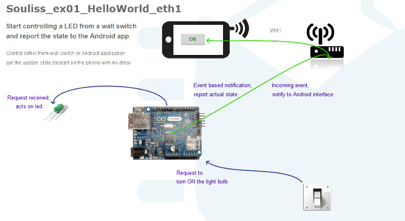
This post shows how to connect IoT platform to Cloud service and how to display sensing data for graphical analysis.
* Scope of post
* Platform : WIZwiki-W7500
* cloud data loger : data.sparkfun.com (Phant.io)
* cloud chart : analog.io
* IDE; Web-Compiler(mbed.com)
* HTTP Query
data.sparkfun.com
- What is Phant?
- Phant is a open source cloud server platform by powered Sparkfun Electronics.
- Sparkfun created data.spartfun.com ,which is a free cloud service running phant. –
- To collect data from your device to cloud service, you just need to register a new stream.
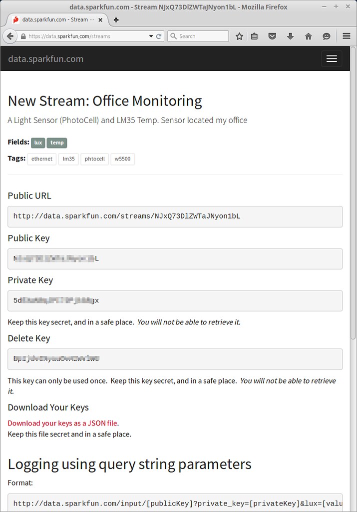
- After register, you get two keys for accessing the data; one is q private key is required to update that stream, other is a public key grants access to any other stream on the service.
- All communication with Phant is carried out over HTTP. So, your device should be acted as HTTP Client.
- http://data.sparkfun.com/input/%5BpublicKey%5D?private_key=%5BprivateKey%5D&%5Bfield1%5D=%5Bvalue%5D&%5Bfield2%5D=%5Bvalue%5D
-
Phant : Phant.io
Phant is a modular node.js based data logging tool for collecting data from the Internet of Things. It is the open source software that powers data.sparkfun.com, and is actively maintained by SparkFun Electronics. Phant is short for elephant. Elephants are known for their remarkable recall ability, so it seemed appropriate to name a data logging project in honor of an animal that never forgets.
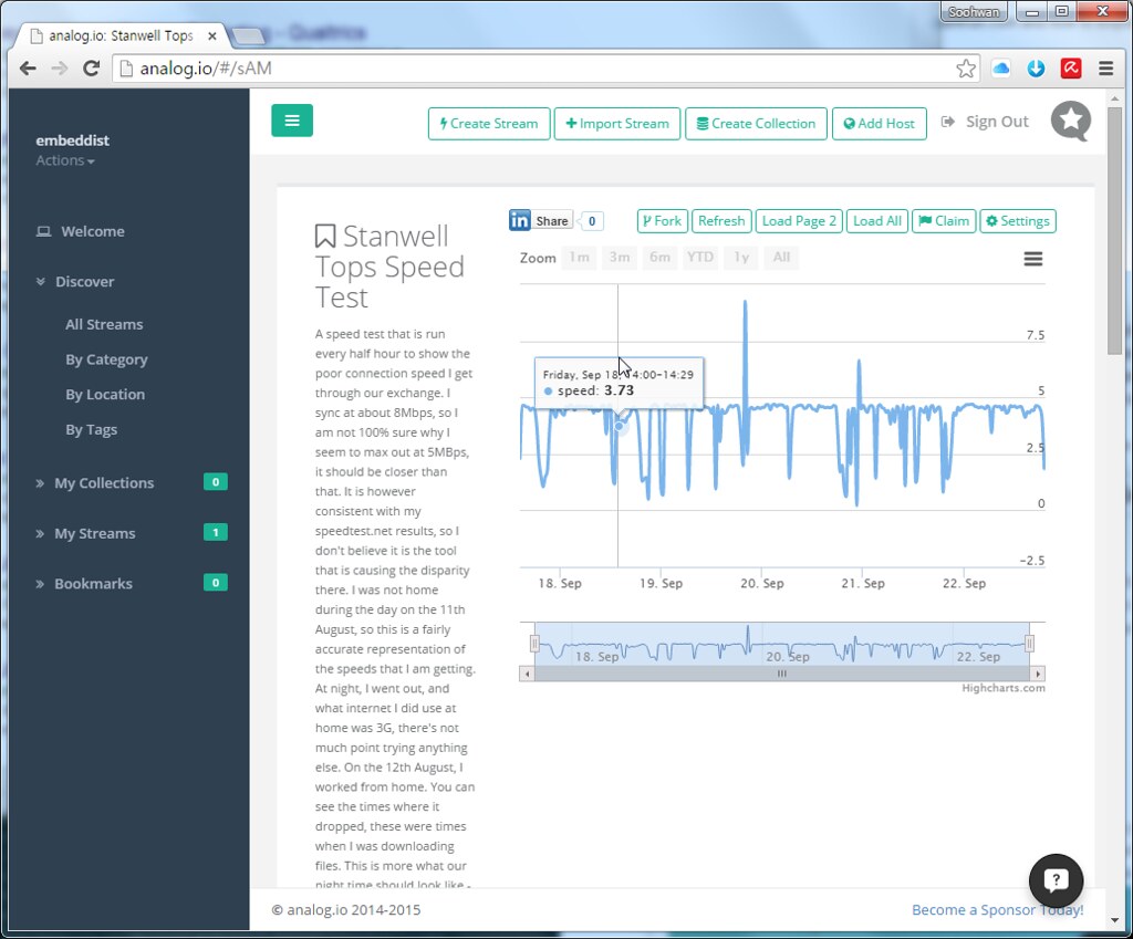
analog.io
- 3rd party of data.sparkfun.com
- Graphing front end
>analog.io is a full stack IoT web service and hardware platforms where people can create connected devices and share them with the world. It is designed to solve all kinds of world problems from air pollution, improving farm output or studying the bee population. It is really only limited by the users imagination. (for more detail)
 //embedr.flickr.com/assets/client-code.js
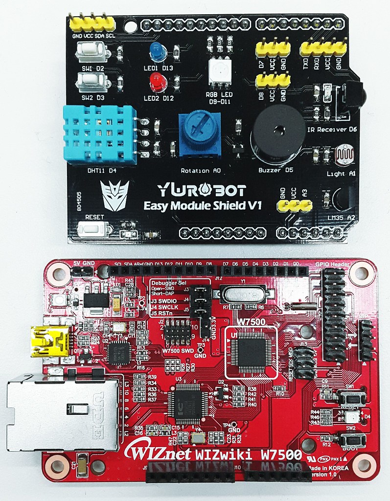
Prepare materials
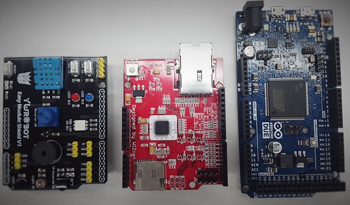
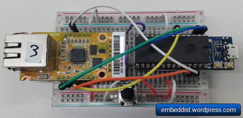
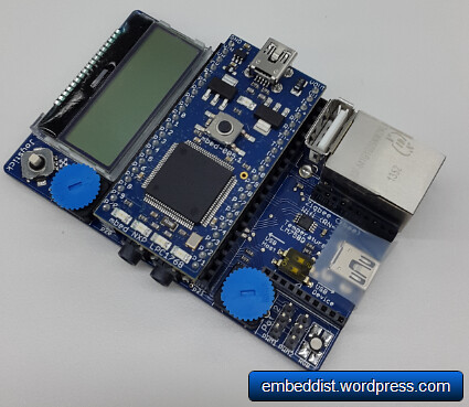
- Hardware
 //embedr.flickr.com/assets/client-code.js
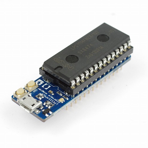
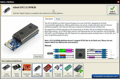
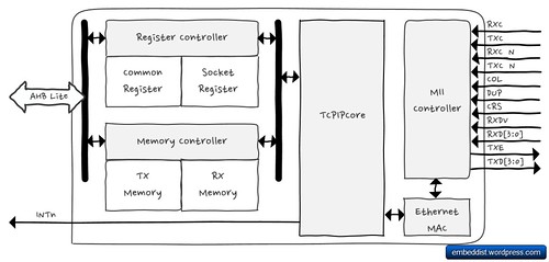
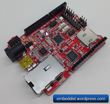
- mbed platform : WIZwiki-W7500
- ARM® Cortex™-M0 Core 48MHz
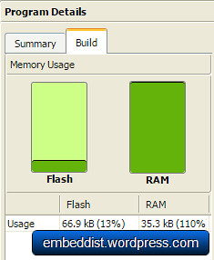
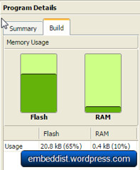
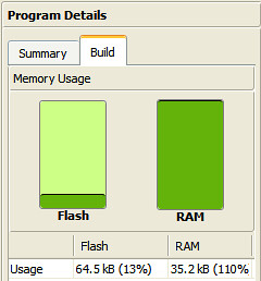
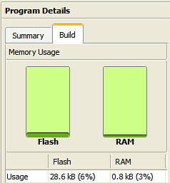
- 128KB Flash memory
- 16KB to 48 KB SRAM (Min 16KB available if 32KB socket buffer is used, Max 48KB available if no socket buffer is used)
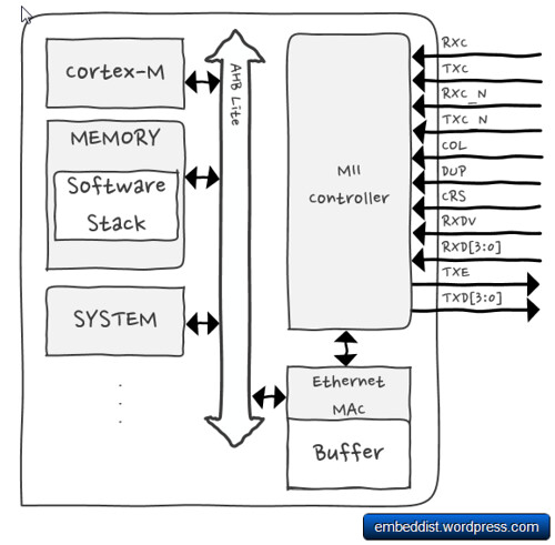
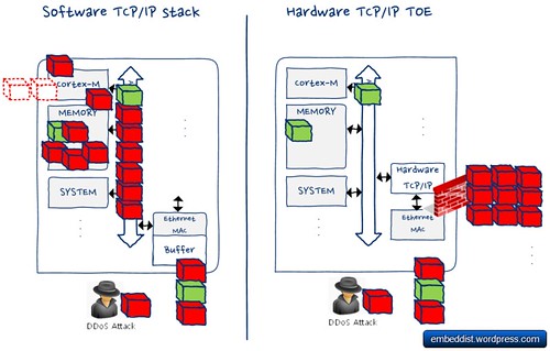
- Hardwired TCP/IP Core (8 Sockets, MII: Medium-Independent Interface)
- 12-bit, 8ch ADC
- 53 I/Os
- 1ch Watchdog, 4ch Timers and 8ch PWM
- 3ch UART
- 2ch SPI
- 2ch I2C
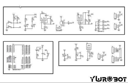
- Sensors (ywrobot easy module shield v1): DHT11
 //embedr.flickr.com/assets/client-code.js
- mbed platform : WIZwiki-W7500
-
Registrations
- data.sparkfun.com
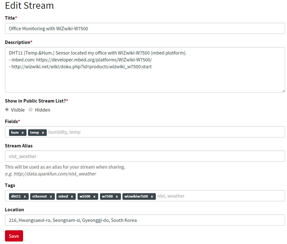
To create a data stream, head over to data.sparkfun.com, and click “CREATE”.- Create a Data Stream
 //embedr.flickr.com/assets/client-code.js
* Fields – This comma-separated list of words defines data stream to post a list of unique values.
* Stream Alias – This testbox defines domain name for you Data Stream -
New Stream example: After creating a data Stream, you will confirm URL, Keys for accessing for your data stream.
 //embedr.flickr.com/assets/client-code.js
- Create a Data Stream
- data.sparkfun.com
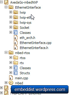
Software
 //embedr.flickr.com/assets/client-code.js
* Used Lib
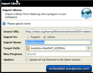
* WIZnetInterface Lib. : for Ethernet connectivity of W7500
* DHT Lib. : for DHT11 sensor
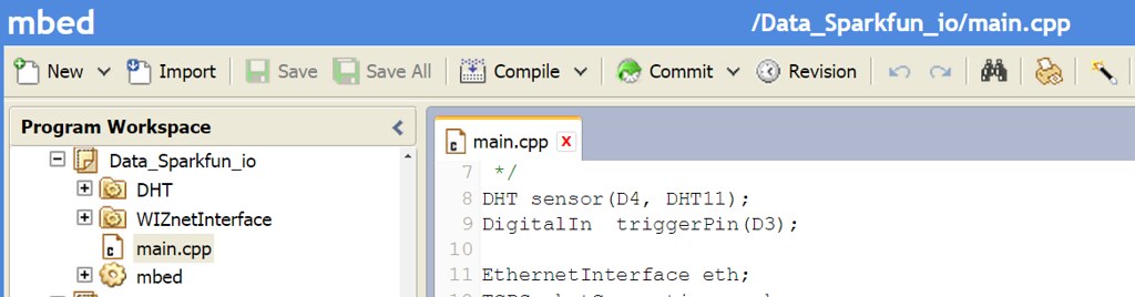
Codes flow
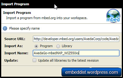
- mbed.org repositories : https://developer.mbed.org/users/embeddist/code/Data_Sparkfun_io/
-
Configuration Arduino’s I/O pins
/*
 *Input Pins, Misc
 * D4 - Temp. and Hum. Sensor
 * D3 - Push buttom
 */
DHT sensor(D4, DHT11);
DigitalIn  triggerPin(D3);
- Configuration Phat Stuff
/*
 * Phant Stuffs
 * Insert your publicKey
 * Insert your privateKey
 * Generat Fileds; 'Files name shoud be same "field name" in Create Stream form'
 */
char publicKey[] = "insert_your_publicKey";
char privateKey[] = "insert_your_privateKey";
uint8_t NUM_FIELDS = 2;
char fieldNames1[] = "hum";
char fieldNames2[] = "temp";
- Network Configuration : DHCP Client
   // Enter a MAC address for your controller below.
    uint8_t mac_addr[6] = {0x00, 0x08, 0xDC, 0x00, 0x01, 0x02};

    printf("initializing Ethernetrn");
    // initializing MAC address
    eth.init(mac_addr);

    // Check Ethenret Link
    if(eth.link() == true)   printf("- Ethernet PHY Link-Done rn");
    else printf("- Ethernet PHY Link- Failrn");

    // Start Ethernet connecting: Trying to get an IP address using DHCP
    if (eth.connect()<0)    printf("Fail - Ethernet Connecing");

    // Print your local IP address:
    printf("IP=%snr",eth.getIPAddress());
    printf("MASK=%snr",eth.getNetworkMask());
    printf("GW=%snr",eth.getGateway());
- HTTP Client
/*
 *  - If the trigger pin (3) goes low, send the data.
 *      - Get sensing datas by using analogread()
 *      - Call postData
 *          - Open socket as TCP Client
 *          - Try to connet TCP server (data.sparkfun.com); if needs, do DNS clinet for getting IP address of server
 *          - Make query string based on Phant frame
 *          - Send query
 *          - Check for a response from the server, and route it out the serial port.
 */

    while(1)
    {
        if(triggerPin ==0)
        {
            sensor.readData();
            c   = sensor.ReadTemperature(CELCIUS);
            h   = sensor.ReadHumidity();
           printf("Temperature in Celcius: %4.2f", c);
           printf("Humidity is %4.2fn", h, dp, dpf);

          sock.connect("data.sparkfun.com", 80);

          snprintf(http_cmd, http_cmd_sz,  "GET /input/%s?private_key=%s&%s=%2.2f&%s=%3.3f HTTP/1.1rnHost: data.sparkfun.comrnConection: closernrn",
                                            publicKey, privateKey, fieldNames1, h, fieldNames2, c);
          sock.send_all(http_cmd, http_cmd_sz-1);

          while ( (returnCode = sock.receive(buffer, buffer_sz-1)) > 0)
          {
              buffer[returnCode] = '';
              printf("Received %d chars from server:nr%sn", returnCode, buffer);
          }

          sock.close();
        }

        wait(2);
    }
-
Make Query string over HTTP
http://data.sparkfun.com/input/%5BpublicKey%5D?private_key=%5BprivateKey%5D&hum=%5Bvalue%5D&temp=%5Bvalue%5Dsnprintf(http_cmd, http_cmd_sz, "GET /input/%s?private_key=%s&%s=%2.2f&%s=%3.3f HTTP/1.1\r\nHost: data.sparkfun.com\r\nConection: close\r\n\r\n", publicKey, privateKey, fieldNames1, h, fieldNames2, c); sock.send_all(http_cmd, http_cmd_sz-1);
Demo
Serial Monitor
- DHCP Clinet message
- Press the button to send query to server.
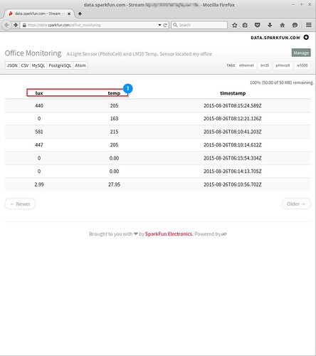
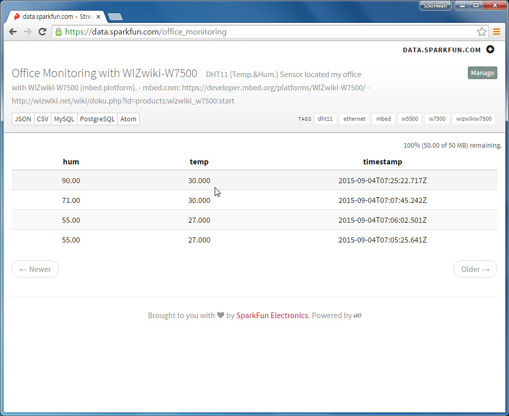
- Confirm the response message on serial terminal and data.spark.com/your_stream
initializing Ethernet
- Ethernet PHY Link-Done
IP=192.168.11.224
MASK=255.255.255.0
GW=192.168.11.1
Temperature in Celcius: 27.00Humidity is 55.00
Received 299 chars from server:
HTTP/1.1 200 OK
Access-Control-Allow-Origin: *
Access-Control-Allow-Methods: GET,POST,DELETE
Access-Control-Allow-Headers: X-Requested-With, Phant-Private-Key
Content-Type: text/plain
X-Rate-Limit-Limit: 300
X-Rate-Limit-Remaining: 298
X-Rate-Limit-Reset: 1441353380.898
Date: Fri, 04 Sep 20
Received 299 chars from server:
15 07:46:03 GMT
Transfer-Encoding: chunked
Set-Cookie: SERVERID=phantworker2; path=/
Cache-control: private
https://data.sparkfun.com/office_monitoring
 //embedr.flickr.com/assets/client-code.js
analog.io: import stream from data.sparkfun.com/your_stream
- How to Import Stream
-
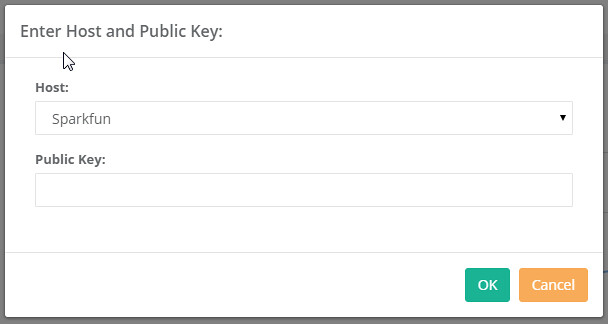
Click ‘+Import Stream’ button on menu
 //embedr.flickr.com/assets/client-code.js
 -
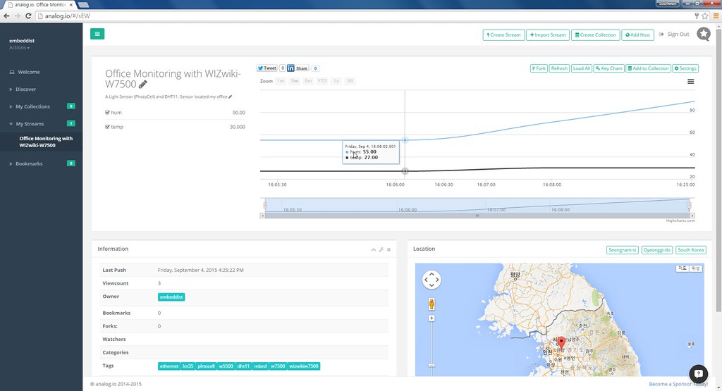
Select ‘Sparkfun’ on Host drop box and input Public key of data.sparkfun.com
 //embedr.flickr.com/assets/client-code.js
 - Confirm your Stream
 //embedr.flickr.com/assets/client-code.js
-