I tried to make the WiFi Shield for GR-KURUMI.
For GR-KURUMI WiFi shield, WizFi250 is select as WiFi module which provides UART-to-WiFi and SPI-to-WiFi.
To test simply, FI250 library which is selected UART interface for Host Interface is used as WiFi Library.
Ref. : Comparison of WizFi250 (WiFi Module) Shield / Library in WIZnet and Seeeduino
GR-KURUMI and WizFi250 could be connect to “Serial1”: serial1 is UART interfae which is consist TXD(7) and RXD.(8) as below GR-KURUMI Pin map.

GR-KURUMI Pin Map
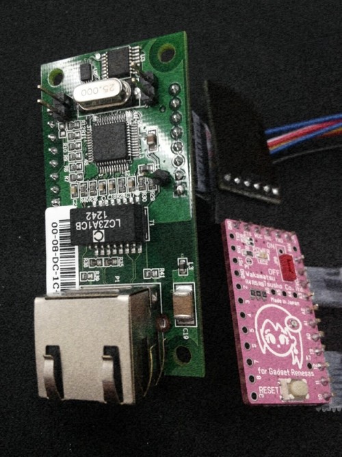
1. Hardware
- Hardware conntections
|
GR-KURUMI |
WizFi250 |
|
7 |
TXD:JP2 |
|
8 |
RXD:JP2 |
|
GND |
GND |
|
VCC |
TP2 |
Follow these steps to connect the actual, is as shown in the following figure.
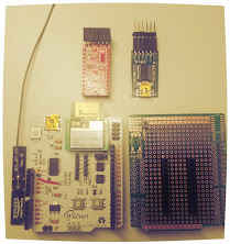
1. prepare GR-KURUMI, WizFi250, WizFi250-EVB, FTDI board, Bread board, Ext. Anttena

2. connect TP2 to 3.3V in JP5 for 3.3 power input of GR-KURUMI
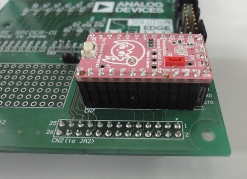
3. Wiz250 (WiFi Shield) bottom for GR-KURUMI: Connect TXD@JP2 to AD1@JP7 and Connect RXD@JP2 to AD0@JP7

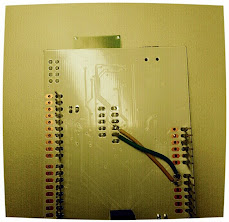
4.1 Interface board (WiFi Shield) top for GR-KURUMI

4.2 Interface board (WiFi Shield) bottom for GR-KURUMI : Red : 3.3V / White : GND / Green : RXD / Yellow : TXD / Blue: WizFi250 RESET
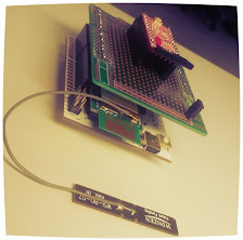
5. Stack up with Wiz250 (WiFi Shield), Interface board and GR-KURUMI
2. Software
* Library
I forked Fi250 Library at Fi250 Webpage.
Lib. is modified for GR-KURUMI and added some function.
Lib. is upload at Github : https://github.com/embeddist/Seeeduino_WizFi250
* IDE : IDE for GR 0.4.0
3. programming and debugging interface
* programming interface

GR-KURUMI Programming
* debugging interface : USB Interface (power & USART1)

WizFi250-EVB
4. Set Sketch: wizfi250_test.ino
__Before setting wizfi250 example, you should be import the WizFi250 Lib. at IDE for GR. __
#define SSID “STEST” //Input SSID
#define KEY “87654321” // Input Password
#define AUTH “WPA2” // Input Encrytion Type#define wizfi250_rst 9 // Chech and Set wizfi250 hw reset pin
- Demo: Debugging Messages
AT
[OK]
AT+WSET=0,3PA-W //SSID of AP
[OK]
AT+WSEC=0,WPA2,wiznet— // password
[OK]
AT+WNET=1
[OK]
AT+WJOIN
Already Associated : Station Mode
[OK]
AT+WSTAT
IF/SSID/IP-Addr/Gateway/MAC/TxPower(dBm)/RSSI(-dBm)
STA/3PA-W/192.168.123.136/192.168.123.254/00:08:DC:1C:D8:73/31/33 //DHCP IP address and Info… from AP
[OK]
 (via
(via 


 PWDN, nINT signals are not used.